|
|
Previous: Analgoue Electronic Switching
|
|
Empress, System X and the digital network
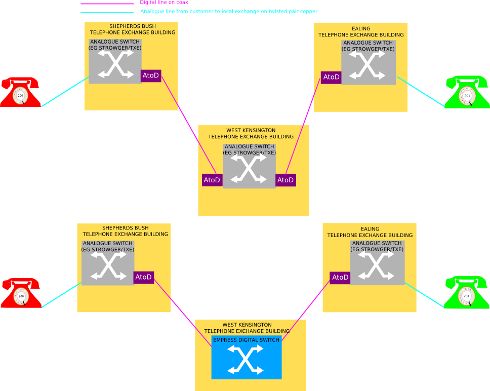
Post Office scientists also scored a world first in 1968 with the first digital exchange, installed at West Kensington exchange in London. It was described as a major step towards a telecommunications system that is fast, efficient and cheap and can take any form of traffic - voice, vision and data. It is easy to forget how rapidly technology was developing. In the early stages of the Empress design a study had to be made of the range of integrated circuits (IC's) that would be suitable and diode-transistor logic (DTL) was chosen. However by the end of the development stage transistor-transistor logic (TTL) was available with significant speed improvements. Empress remained in use for several years. Re-using many ideas from earlier solid state experiments such as Highgate Wood, the earlier problems were all but eliminated by the use of digital signals rather than the noisy analogue ones, coupled with the newer components now available.
Empress exchange as it was dubbed, acted as a tandem switching point relaying calls between several other exchanges in West London such as Ealing and Shepherds Bush.
|
The process of converting analogue signals to digital had been invented back in 1937 by British scientist Alec Reeves. Known as pulse code modulation (PCM) it involves sampling the strength (amplitude) of the analogue signal at intervals and then encoding the sampled amplitude as a binary number which can then be stored, switched and transmitted. Today PCM is at the heart of all digital phone networks, radio, TV, cameras and music. Back in the 60''s the Post Office had begun using PCM digital lines between exchanges as a way of more efficiently carrying multiple phone circuits on one cable over long distances without the noise and signal degradation problems suffered with the older analogue circuits. These inter-exchange circuits known as 'junctions' and 'trunks' had to be converted back to analogue at the distant end - they were simply a point to point wire - any time routing/switching was needed the signal had to be converted back to analogue, switched through an analogue exchange such as a Strowger or Crossbar electromechanical exchange or maybe one of the new reed relay electronic exchanges and then converted back to digital to send it on its way again.
|
|
 |
The obvious next step was to design a fully digital exchange so that phone calls could remain in digital format throughout the network, needing only to return to analogue near the customer. Empress was fully digital and fully solid state
and proved to be the first switching of live telephone traffic digitally in the world and its success spurred
on the development of a production ready digital system which could be installed nationwide to replace not only
the electromechanical Strowger and Crossbar systems but also the relatively new reed relay analogue electronic systems too.
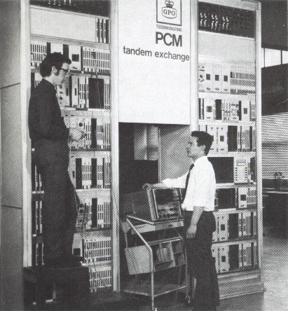
This system came to be known as System X
|
|
From its inception in 1968 contracts with the three principal suppliers (GEC, Plessey and STC) were signed in 1973 and System X made its World debut at the Geneva Telecom Exhibition in 1979. This was seen as a great success for British Telecommunications.
System X saw the introduction of digital switching right across the country with software controlled ('Stored Program Control') exchanges designed to cover from small local exchanges (local exchanges being those in towns/villages to which customers lines are directly connected) to large trunk and international gateway exchanges.
System X was designed from the outset as a modular architecture of subsystems each of which was self contained and had clear boundaries allowing each subsystem to be developed somewhat independently and evolve in the future without affecting backward compatibility with the rest of the system. This lead to the development of a range of sub-systems, perhaps the most important being the digital switching sub-system (DSS) which forms the heart of a System X exchange and the processor Utility sub-system (PUS) which is the central control computer.
|
|
|
The PUS has evolved greatly over the years, as new computer hardware has become available. In 1987 a System X exchange broke the world record for simultaneous call handling capacity under the watch of independent judges. The control software has also evolved over the years, and indeed largely been
re-written in C (originally it was written in CORAL) and the real-time operating system replaced with a more modern and advanced off the shelf
system LynxOS - a 'Unix-like' real time operating system from LynuxWorks.
The other major subsystem is the Digital Subscriber Switching Subsystem (DSSS) which is the part to which customers lines are directly connected. The DSSS concentrates up to 4096 lines down into between 2-16 digital links each of which can carry up to 30 calls simultaneously.
The first System X local exchange was opened in Woodbridge Suffolk in 1981 and from 1983 onwards installation progressed across the country.
Now the phone line was about far more than having a conversation between two people, System X introduced new services such as 3 way calling, automatic alarm calls, call barring, caller display and ISDN. ISDN (Integrated Services Digital Network) extended the digital network from the local exchange to the customers premesis using a digital line. Conventional phone lines are still analogue between the customer and exchange, even on digital exchanges This weak link in the chain reduces data throughput (see side box on PCM) and introdces noise.
ISDN, by using a digital link end to end, offers the full data rate available over the phone network and crystal clear sound.
As described in the side box on PCM, each line is 64kbits/sec. ISDN offered the facility to multiplex together 2 or 30 digital lines as one connection giving a variable data rate of 64kbits upto 2Mbits but with the associated cost of 30 simultaneous phone calls! Although ISDN is popular in the radio world for carrying out remote interviews with crystal clear sound, it never gained widespread popularity as a means of computer data transfer, primarily due to its high cost.
Growth of System X was rapid, in just 4 years 55 exchanges were put in place. Early System X roll-out plans from 1983 show
Crossbar and TXE4 remaining in use until 2014! The target was to replace all the large Strowger exchanges by 1992 which was achieved .
The last Crossbar exchanges were replaced by 1994. The very last being at Droitwich Worcestershire. TXE2 exchanges and the very last Strowger
exchanges were gone by June 1995 leaving just the TXE4 large analogue reed relay system operating in some areas.
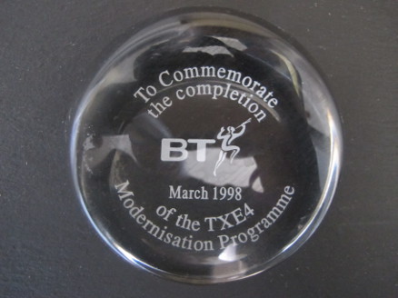
These too were replaced by March 1998 when the whole BT network become completely digital.
|
|
|
|
|
|
First System X exchanges brought into service (BIS) in order. First two local exchanges were at Woodbridge Suffolk & Arrington Cambridge. First trunk exchange was at Cambridge
| No |
Type & Location |
BIS Date |
| 1 |
DJSU Baynard House |
July 80 |
| 2 |
DLSU Woodbridge |
July 81 |
| 3 |
DJSU Baynard House
(replaced switch No.1) |
July 81 |
| 4 |
DLSU Arrington |
Dec 81 |
| 5 |
DMSU Cambridge |
Dec 81 |
| 6 |
DLSU Hale |
Jun 83 |
| 7 |
DMSU SEP* Coventry Spires |
Dec 83 |
*System Enhancement Programme - the first evolution to the Sys X family. This was the first
exchange to be brought into service after SEP.
DLSU = Digital Local Switching Unit i.e a local exchange (one with customers lines directly connected to it)
DJSU = Digital Junction Switching Unit - a tandem exchange i.e one routing traffic between several DLSUs
DMSU = Digital Main Switching Unit - a trunk exchange (an exchange handling long distance traffic routing between many DLSus and DJSUs)
If anyone has info on any
other switch BIS dates (regardless of where they fit in the table) please get
in touch.
System
X Digital Main Switching Unit Sites - 1999 |
| Aberdeen |
Leeds (2) |
Norwich |
| Birmingham (4) |
Leicester (2) |
Nottingham |
| Bishops Stortford |
Liverpool |
Oxford |
| Bradford |
London (Ilford) (2) |
Peterborough |
| Bristol (2) |
London Baynard (City) |
Plymouth |
| Cambridge |
London (Colindale) (3) |
Portsmouth |
| Cardiff |
London Cranmer (Croydon) |
Preston |
| Carlisle |
London Grenville (Eltham) |
Reading (2) |
| Chelmsford |
London North Paddington |
Salisbury |
| Chester |
London Palmerston (Wood Green) |
Sheffield (2) |
| Clyde Valley |
London Southbank (2) |
Shrewsbury |
| Coventry |
London Tower (West End) (2) |
Slough |
| Crawley (2) |
London Walpole (Ealing) |
Southampton |
| Darlington |
Luton |
Stoke |
| Edinburgh (2) |
Maidstone |
Swansea |
| Exeter |
Manchester (3) |
Swindon |
| Glasgow (2) |
Milton Keynes |
Tunbridge Wells |
| Gloucester |
Newcastle |
Warrington |
| Guildford |
|
Wolverhampton |
| Ipswich |
|
York |
NOTE: Figures in brakcets indicate actual number of switches, which may or
may not be colocated.
|
|
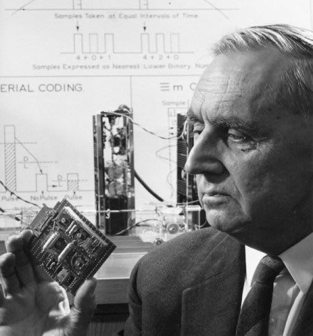 |
Alec Reeves
Inventor of Pulse Code Modulation. Today all analogue signals such as speech from a microphone or light falling on a CCD sensor is converted to a digital signal using PCM.
|
 |
|
|
Above is an analogue signal such as that from a microphone. Time progresses from left to right
and the signal varies in strength (amplitude) up and down
|
 |
|
|
PCM samples the signal at time intervals many times per second and measures the strength (amplitude)
of the signal at that instant. The faster we sample the better representation of the original signal we get, but the
more data we produce which has a cost to store or transmit. The amplitude of each sample is stored as a binary (digital) number
|
 |
|
|
The analogue signal has to be re-created to be sent to a speaker. Here we can see we don't get back exactly the
same as the original signal because our sampling frequency was low. For telephone speech our ears don't notice so we can get away with it and save on transmission cost. For music a high sampling frequency is needed.
US Researcher Harry Nyquist discovered that to recover the signal adequately you need to sample at at least 2x the highest frequency in the original signal. Human voice tends to max out at around 3.4kHz so phone signals are sampled at 8kHz. 8 bits are used to represent each sample giving a bit rate per line of 64kbits/sec (8000x8=64000). The telephone system switches paths of 64kbit/sec through the network. In the USA it's 56kbits/sec as some of the bits are used for other things hence the reason why modems have never been marketed operating above this speed.
This then is theoretically the maximum speed you can get from a dial up data connection, however this is only possible using ISDN which is digital end to end. With a conventional analogue phone line the data goes through a digital-analogue conversion at either end reducing throughput slightly. Dial up modems therefore, although capable of 56kbits/sec, tend to max out around 48kbits/sec.
|
|
|